
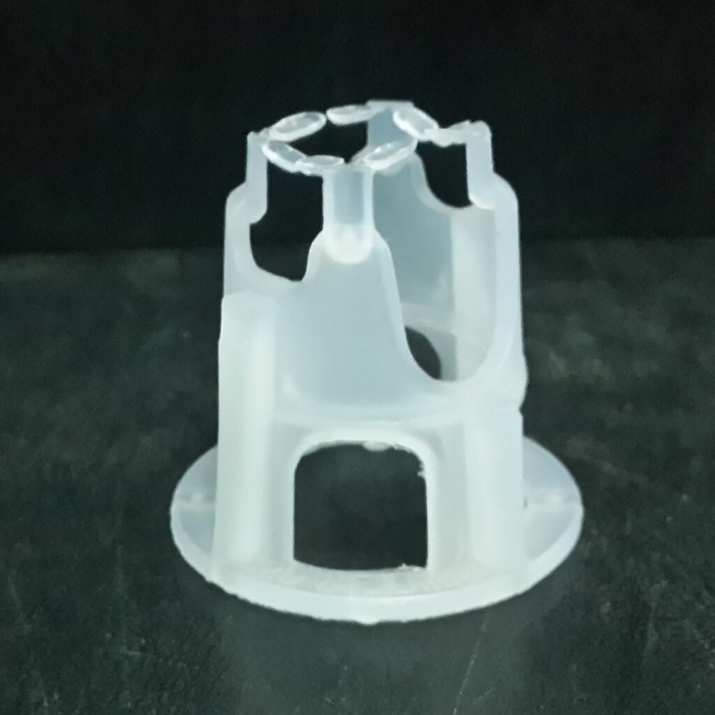
What is concrete cover?
Concrete cover is the distance between reinforcement and the nearest concrete surface. On a site this is not a number to guess from the cover block packet—the required value comes from the structural drawing and project specification.
Once the required cover is known, the spacer should hold the relevant steel at that distance from the shuttering or concrete face. The correct product therefore depends on cover dimension + steel arrangement + application.
Why correct cover matters
Concrete cover protects the steel and forms part of the intended RCC section. If cover becomes too small at a local point, steel can be exposed sooner to moisture, carbonation, chlorides or fire. If steel is not held in the position shown on the drawing, the reinforcement arrangement itself has also changed.
Cover requirements vary with structural design, exposure and fire requirements. Use the drawing and project specification as the controlling site documents.
Reinforcement has to stay in the drawing position
IS 456 does not treat cover blocks as an optional finishing accessory. Section 12.2 says reinforcement should be placed and maintained in the position shown on the drawings by using proper cover blocks, spacers, supporting bars and similar supports.
Section 12.3.2 then connects the spacer directly with nominal cover: spacers between the steel and formwork should match the required nominal cover, supports should be used to maintain that cover, and closer spacing may be needed where site conditions demand it.
For cover-block material, IS 456 specifically states that spacers/cover blocks should be of concrete of the same strength or PVC. It also gives a maximum 1 m support spacing as a general limit, while noting that closer spacing can be necessary.
A good cover block must do more than give height
A spacer can have the correct nominal height and still fail its job if it moves, rotates, breaks or deforms enough to change the steel position. Site conditions include labour movement, reinforcement adjustment, shuttering work, concrete flow and vibration.
That is why useful spacer performance is about dimension, fixity, stability, load, permanent deformation and concrete flow—not only the number printed on the product.
Provide the required distance between reinforcement and the concrete face.
Remain where the reinforcement detail needs the spacer while work continues.
Keep the orientation that provides the intended cover instead of turning around the steel.
Support reinforcement and normal construction loads without unacceptable deformation.
Leave enough open area so the permanent spacer does not become an unnecessarily large obstruction.
The fixing geometry must suit the actual bar diameters and reinforcement arrangement.
How CROSSLOCK locks
The defining feature of the CROSSLOCK cover-block family is the way it engages the reinforcement. Instead of relying only on weight or one bar, the spacer is designed to locate at the crossing of two bars.
At the crossing, the two steel directions help control the spacer orientation. When the correct bars are fully engaged in the correct slots, the spacer stays associated with the reinforcement it is supporting and is less free to rotate or shift independently.
crossing
Locks at the bar crossing
The diagram explains the reinforcement crossing. The official product photograph remains the reference for actual CROSSLOCK slots, ribs and proportions.
- Locates at a repeatable reinforcement feature.
- Uses two reinforcement directions to control orientation.
- Helps resist rotation around a single bar axis.
- Helps the spacer remain with the steel during normal site handling.
Why fixity matters
If a cover block moves away from the point it is meant to support, or rotates into another orientation, the local cover can change even though the product itself has the correct nominal size.
A single-bar spacer can be perfectly suitable when its clip and geometry provide strong retention. The point is not that every single-bar design is weak—the holding system must be evaluated. CROSSLOCK uses the two-bar crossing specifically to improve positional and rotational restraint.
Concrete should flow through and around the spacer
A cover block stays permanently inside the RCC member. Its shape therefore matters after installation as well as before casting. CROSSLOCK uses a highly open body so concrete can occupy the space within and around the spacer.
CROSSLOCK products have more than 60% void area within their enclosed perimeter, including the smaller sizes. That is substantially above the 25% minimum void-area requirement used by BS 7973-1 for non-cementitious spacers.
Large openings leave space for concrete to pass through the spacer body.
Bottom ribs reduce direct contact with shuttering and help the spacer become less visible after de-shuttering.
Material and geometry need to remain compatible with the concrete environment after casting.
Strength alone is not enough
BS 7973-1 evaluates spacer and chair products through dimensions, point-load strength, permanent deflection after loading, stability and fixity. For cover blocks, that is a useful way to think about site performance: a strong spacer still has to stay in place and retain its working height.
BS 7973-1 requires at least 25% void area within the enclosed perimeter for non-cementitious spacers. CROSSLOCK publishes more than 60%.
The standard uses approximately 3 kN as the heavy spacer point-load classification. This is a spacer classification, not a blanket chair rating.
CROSSLOCK's published/tested spacer performance is approximately 4 kN. Use the relevant test record where a project needs formal verification.
Load capacity is meaningful only if the spacer also retains an acceptable height and remains stable after the load is removed.
Choose by application, cover and steel
Start with the structural drawing. Then match the required cover to the reinforcement arrangement. A slab mesh, beam cage, column cage and footing mat do not all need the same spacer geometry.
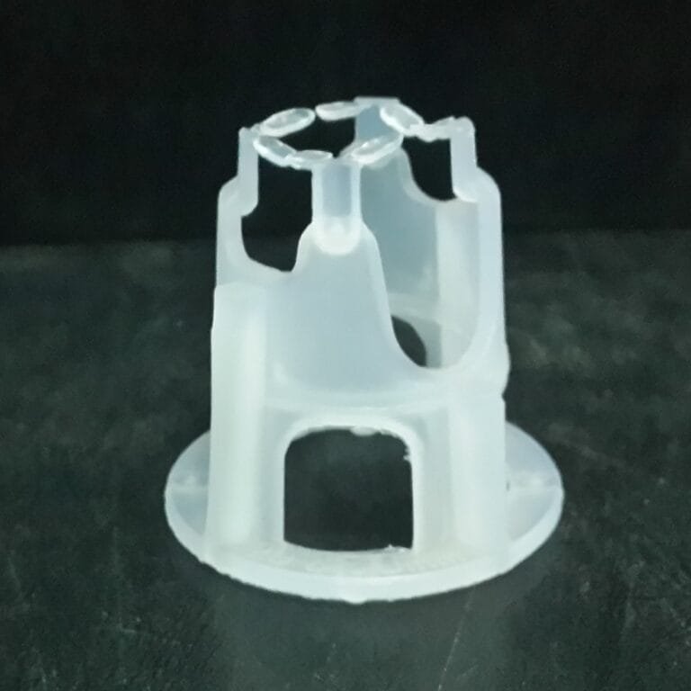
Slab bottom steel
- Concrete cover
- 20 mm
- Compatible bar diameter
- Ask CROSSLOCK
- Planning spacing
- About 2 ft
- Pieces / Packet
- 250
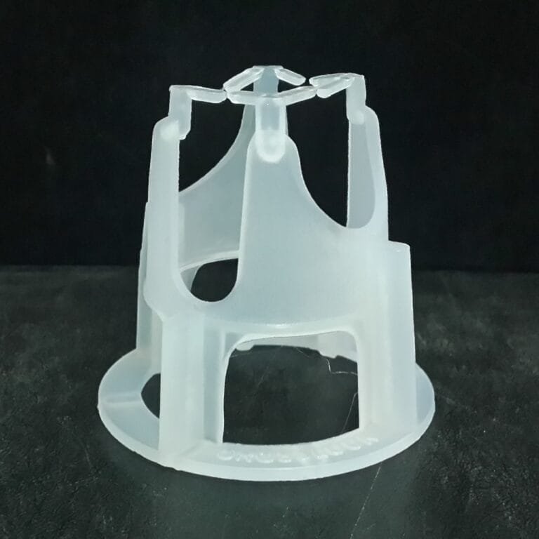
Beam reinforcement
- Concrete cover
- 25 mm to outer ring
- Compatible ring diameter
- Up to 10 mm
- Compatible main-bar diameter
- Up to 25 mm
- Pieces / Packet
- 100
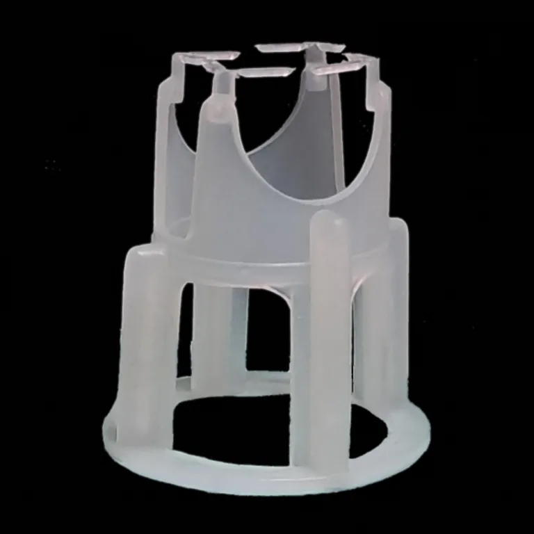
Column / beam side cover
- Concrete cover
- 40 mm
- Compatible ring diameter
- Ask CROSSLOCK
- Compatible main-bar diameter
- Ask CROSSLOCK
- Pieces / Packet
- 75
CLB-40 remains part of the Self-Locking Cover Block family by geometry and is also used as a Vertical Rebar Spacer by application.
See CLB-40 product page → Read the Vertical Rebar Spacer guide →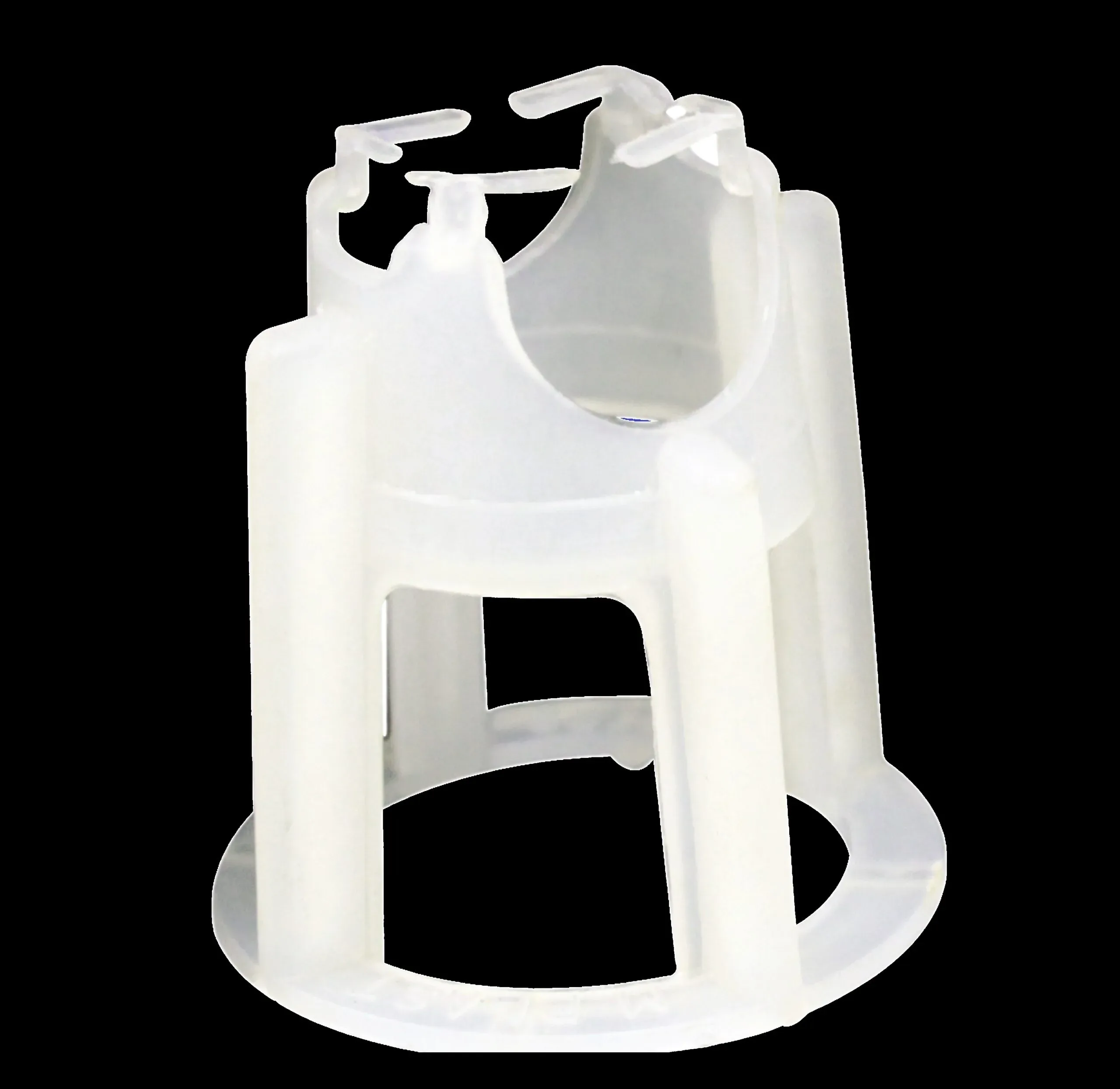
Footing / foundation
- Concrete cover
- 50 mm
- Compatible bar diameter
- Ask CROSSLOCK
- Planning spacing
- About 3 ft + local column zone
- Pieces / Packet
- 65
Top steel is a different support problem. CL-75 and CL-100 are treated as rebar chairs, not ordinary cover blocks. Read the Rebar Chair & Top Reinforcement guide →
Install it at the correct crossing
The practical rule is simple: choose the correct model, put it on the correct steel crossing, and fully engage the bars in the intended slots before concreting.
Lift the mesh temporarily with a brick or only at the point being fitted. Put the lower bar in the lower slot and upper bar in the upper slot, press CL-20 fully at the crossing, then remove temporary supports after the line is fixed.
Install at the crossing of the ring and main bar before the cage is lowered. Avoid a sudden impact on the spacer: temporary balli/wood support can stop the cage just above shuttering, after which the support is removed and the beam is settled gradually.
- Confirm the required cover.Use the structural drawing or project specification before choosing the product.
- Use the intended steel crossing.Match ring/main bar or lower/upper bar with the slots designed for that model.
- Press until fully engaged.Do not leave the spacer hanging loosely or sitting at an angle.
- Check the steel level before casting.Correct any missing, damaged or displaced supports before concrete placement starts.
Use enough spacers to keep the steel level
There is no single spacing that fits every RCC member. The spacing has to keep reinforcement at the required cover without local sagging or movement. Bar diameter, steel stiffness, reinforcement arrangement and site loading all matter.
For planning, MPLAST commonly uses about 2 ft for CL-20 slab bottom steel, two CLB-25 pieces at about 3 ft intervals along beams, and about 3 ft for CL-50 footing mats with extra support under the column zone. Drawings and site conditions can require closer support.
Use the quantity calculator for packet planning after confirming the site requirement.
Actual beam width and reinforcement arrangement can change the requirement.
Add local support where the column cage places concentrated load on the footing mat.
Compare cover block options fairly
Manufactured cementitious spacers can provide controlled dimensions and can be suitable when their strength, quality and fixing meet the project requirement. The common site concern is with inconsistent or low-quality pieces: weak strength, high porosity, poor local contact and unreliable fixing can create problems in the cover zone.
Plastic spacers can provide accurate dimensions and quick installation. Their performance still depends on geometry and retention. A single-bar design with good fixity can work well; a weak grip can rotate or become displaced. CROSSLOCK takes a different approach by locking at a two-bar crossing.
Codes & technical references
- IS 456:2000 — Plain and Reinforced Concrete — Code of Practice, especially Sections 12.2 and 12.3.2 for reinforcement position, cover, support spacing and spacer material.
- BS 7973-1:2001 — Spacers and chairs for steel reinforcement — Product performance requirements, covering dimensions, point load, permanent deflection, stability and fixity.
- The Concrete Society — Spacers and chairs.
- MPLAST INDUSTRIES — CROSSLOCK brochure and relevant product test records.
Common questions
Why is it called CROSSLOCK?
The defining concept is that the spacer locks at the crossing of two reinforcement bars. The crossing gives it two steel directions for positional and rotational restraint.
Is CROSSLOCK simply another PVC cover block?
PVC describes an allowed spacer material under IS 456. CROSSLOCK describes a product family and its crossing-lock geometry. Material alone does not explain fixity, void area, load performance or bar compatibility.
Does self-locking mean the steel does not need tying?
No. Reinforcement tying and fixing remain necessary. Self-locking describes the spacer's engagement with reinforcement, not the fixing of the whole reinforcement cage or mesh.
Why does rotation of a cover block matter?
If a spacer rotates into a different orientation, its effective distance between steel and shuttering can change. Fixity therefore matters in addition to nominal spacer height.
Can I choose the cover from the product list?
No. First check the structural drawing or project specification. The product list helps you choose a spacer only after the required cover is known.
Are cementitious cover blocks always wrong?
No. Properly manufactured cementitious spacers can be suitable. Strength, quality, porosity, size and fixing need to meet the project requirement. The concern is mainly with inconsistent or weak products, not the entire material category.
Is a rebar chair a cover block?
They are both reinforcement supports, but their site jobs are different. A cover block maintains cover to a concrete face. A rebar chair primarily supports top steel at the required level. CL-75 and CL-100 are treated separately as rebar chairs.
Does the 3 kN heavy-spacer figure apply to rebar chairs too?
No. The approximately 3 kN figure is a heavy-spacer point-load classification in BS 7973-1. The standard treats chair testing separately, so the spacer classification should not be copied directly onto rebar chairs.
Ask CROSSLOCK about your site
Send the RCC member, required cover, ring/main-bar sizes or slab steel arrangement, and a drawing/photo if available. We can help identify the sensible product and quantity-planning route.